
Technical Bulletin: More Electrical Changes in Marina Code
Published on June 26, 2018


Editor’s Note: This article, thanks to expert Gary Loftis will explain the intent and purpose of the Tentative Interim Amendment (TIA) by National Fire Protection Agency (NFPA). It will explain the new definitions and how they impact marinas electrical systems; break down and explain the language of the TIA’s Ground-Fault Protection requirements; explain where Ground-Fault Protection is and is not required in the marina’s electrical system; and explain and provide examples of Ground-Fault Protection coordination. References include: 1. 2017 NFPA 70 – National Electrical Code; 2. NFPA Tentative Interim Amendment 17-15 (SC 18-4-4 / TIA Log #1348); and 3. US Coast Guard report “In-Water Shock Hazard Mitigation.” Portions of these reference documents are directly quoted within this bulletin. Credit is given to their respective authors.
Introduction
The National Fire Protection Association (NFPA) has made some significant changes to the current 2017 National Electric Code (NEC) that will affect the marina industry. Many in the marina industry felt the restrictions in the 2017 NEC were not practical to function in the real marina environment. NFPA listened to the marina industry and took action to change these requirements. These changes are made by a Tentative Interim Amendment (TIA). A TIA is a mechanism by which NFPA can make changes to an existing standard. In this case, a TIA has been issued that changes the Ground-Fault Protection requirements for marinas.
Most existing marinas today are not required to upgrade to the 2017 NEC  because the new NEC only applies to new construction. This is true for all electrical code changes explained in this document. When a marina’s electrical system is installed, it must be installed under the adopted code at time of installation. When a new code edition is issued, an existing marina is not required to retroactively update its electrical system to the new code standards, unless the local authority having jurisdiction requires it, which is rare. Therefore, the 2017 edition of the NEC, including the TIA (which is the topic of this document) applies only to new construction projects or expansions to an existing marina’s electrical system.
TIAs are issued from NFPA for the purpose of adding to, changing, and/or clarifying existing code language between the period of standard publications. When a TIA is approved and published, it amends the current code standard and becomes new code. In the case of the NEC, which is published every three years, a TIA can be issued between the three-year code revision cycle. Also, the TIA is automatically treated as public input considered for inclusion and/or as a revision of the TIA in the next code edition.
The referenced TIA2 is the latest change to the 2017 Edition of the NEC and was effective as of April 30, 2018. This TIA provides two new definitions and changes the Ground-Fault Protection requirements for marinas.
The language of the two new definitions in the TIA are listed below:
Docking Facility. A covered or open, fixed or floating structure that provides access to the water and to which boats are secured.
Marina. A facility, generally on the waterfront, that stores and services boats in berths, on moorings, and in dry storage or stack storage.
These definitions define the parts of the marinas that are used for the mooring of vessels. The importance of these definitions will become apparent as this discussion continues on Ground-Fault Protection.
TIA – NEC Article 555.3 Ground-Fault Protection
The following is the language of the TIA. Remember, this language changes the existing language of the 2017 Edition NEC Article 555.3 Ground Fault Protection.
“555.3 Ground-Fault Protection. For other than floating buildings covered by 553.4, ground-fault protection for docking facilities shall be provided in accordance with (A) and (B).
(A) Feeder and Branch Circuit Conductors. Feeder and branch circuit conductors that are installed on docking facilities shall be provided with ground-fault protection set to open at currents exceeding 30 mA. Coordination with downstream ground-fault protection shall be permitted at the feeder overcurrent protective device.
Exception: Transformer secondary conductors of a separately derived system that do not exceed 3 meters (10 feet) and are installed in a raceway shall be permitted to be installed without ground-fault protection. This exception shall also apply to the supply terminals of the equipment supplied by the transformer secondary conductors.
(B) Receptacles Providing Shore Power. In lieu of the requirement of 210.8, receptacles installed in accordance with 555.19(A) shall be permitted to have ground-fault protection set to open at currents not exceeding 30 mA.” 1
The explanation of this language will be divided into three parts; Part 1 will provide introduction comments and principles of the new language; Part 2 will explain section noted as “(A) Feeder and Branch Circuit Conductors;” and Part 3 will explain section noted as “(B) Receptacles Providing Shore Power.”
Part 1
For required context, the following is a definition of “Ground-Fault Protection”
(GFP):
A system or device set to open all ungrounded conductors (i.e. hot conductors) when leakage or fault current of the circuit reaches a pre-set trip level. This pre-set trip level shall be less than the rating of the overcurrent protection device (i.e. breaker) feeding the circuit.
The new NEC language of the TIA 555.3 still requires GFP for all new constructions of marinas. The required trip levels of the GFP devices shall be discussed below.
The TIA brings up the point that “floating buildings” are not including in the requirements of Article 555.3. The GFP requirements for “floating buildings” are found in Article 553.4, where the trip setting of the GFP is required to not to exceed 100 mA. The importance of this is that “floating buildings” within the marina harbor are not included in the requirements of Article 555.3. Therefore, the requirements of Article 555.3 only include the structures, as defined by the new TIA definition “Docking Facility.”
The words “shall be” are definite language requiring both (A) and (B) of the TIA to be followed in the electrical installation of a Docking Facility.
Part 2
The section in the TIA labeled as “(A) Feeder and Branch Circuits Conductors” provides the GFP requirements for all circuits conductors on the docking facility. This means that all conductors after the main disconnect located on the shore shall be protected by a GFP device.
The language of the TIA becomes of greater interest when it talks about the trip setting of the GFP. Consider the original language of the NEC 555.3 2017 Edition:
“555.3 Ground-Fault Protection. The overcurrent protective devices that supply the marina, boatyard, and commercial and noncommercial docking facilities shall have ground-fault protection not exceeding 30 mA.”1
Take special notice to the way the language is written describing the GFP:
“ground-fault protection not exceeding 30 mA.”
There is no doubt that the interpretation of this language was that the GFP shall have a trip setting of 30 mA or less. The main complaint in the marina industry with this code language was that it required the entire marina to be protected by a GFP with a trip setting at 30 mA.
The following is the language of the TIA:
“ground-fault protection set to open at currents exceeding 30 mA”
The TIA removes the word “not” from the original language, thus making the GFP trip setting on feeders and branch circuits have a minimal setting of 30 mA. However, the TIA does not provide a maximum trip level setting for the GFP. It is the choice of the engineer of record who is designing the marina’s electrical system how to design the trip settings of the GFP devices protecting feeders and branch circuits so as to provide a safe and reliable system.
Part 3
The section in the TIA labeled as “(B) Receptacles Providing Shore Power” provides clarity to another major complaint by the marina industry. Before NFPA issued the TIA, the 2017 NEC required a shore power receptacle to be protected by a GFCI device (trip setting between 4 to 6 mA), according to Article 210.8.
The following is the language of the TIA:
“ground-fault protection set to open at currents not exceeding 30 mA.”
Note that this is the same language as in section (A) with the exception of the word “not.” This makes the requirement opposite for the shore power receptacle. Therefore, the GFP trip setting for the receptacle shall be 30 mA or less. This requirement permits the engineer designing the system to specify the trip setting from 30 mA down to a GFCI level to protect the receptacle and to coordinate with upstream GFP devices.
Summary of TIA Requirements
The following are the GFP requirements for conductors and receptacles using the interpretation that the TIA is speaking of trip level “currents:”
(A) Feeder and Branch Circuit Conductors.
“ground-fault protection set to open at trip level currents exceeding 30 mA”
GFP trip setting > 30 mA
(B) Receptacles Providing Shore Power
“ground-fault protection set to open at trip level currents not exceeding 30 mA.”
GFP trip setting <= 30 mA
To be fair, it has been argued that there may be another interpretation of the TIA. This interpterion suggests that in lieu of the TIA meaning trip level “currents,” it means leakage “currents.” For example, if one uses this interpretation, the TIA would read as follows:
(A) Feeder and Branch Circuit Conductors.
“ground-fault protection set to open at leakage currents exceeding 30 mA”
This would require feeder and branch circuit conductors to be de-energized by a GFP if the conductor has a leakage current greater than 30 mA. Therefore, the trip setting of the GFP device protecting the conductor would be required to be set to 30 mA or less.
However, the same interpretation must be applied to the shore power receptacle requirement. For example, if one uses this interpretation, the TIA would read as follows:
(B) Receptacles Providing Shore Power
“ground-fault protection set to open at leakage currents not exceeding 30 mA.”
This would require the shore power receptacle to be de-energized by a GFP, if the receptacle or vessel connected to the receptacle has a leakage current of 30 mA or less. At the same time, the receptacle would not be de-energized, if leakage currents were greater than 30 mA. This is where the interpretation fails. A GFP device does not function in this way. This would allow leakage currents above 30 mA to remain at the receptacle and therefore allowing for an unsafe condition.
GFP Coordination
The TIA also allows the engineer to coordinate the GFP devices in the system. There are two ways to provide coordination. The first way is to step the trip settings of the GFP devices. This can be achieved by having the highest trip setting protecting the feeders, a lower trip setting protecting branch circuits, and the lowest trip setting protecting the shore power receptacle. The second way is to put a time delay in the GFP devices. For example, the engineer could specify a 100 mS delay in the GFP at the shore power receptacle, a 150 mS delay in the GFP protecting the branch circuits, and a 200 mS delay in the GFP protecting the feeders. Of course, both of these types of coordination can be implemented in the same system.
GFP Exception
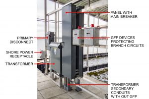
The only exception that allows conductors to be unprotected on a marina is where they are located between the secondary side of a transformer and the line side of the equipment where these conductors terminate. This exception also requires these conductors to be limited to 10 feet in length and installed in a raceway. Be aware, however, that the only approved raceways that can be installed above the deck as listed in Article 555.13 (5) are Rigid Metal Conduit (RMC), Rigid Polyvinyl Chloride (PVC), and Reinforced Thermosetting Resin Conduit (RTRC). Note that “Liquidtight” conduit is no longer approved to be installed above the deck.
The photo on page 32 shows a standard installation of a transformer on a docking facility. The conductors on the secondary side of the transformer to the main breaker located in the panel are not protected by a GFP. However, the secondary conductor length is less than ten feet and is run in PVC conduit. Also, all branch circuit conductors are protected by GFP devices.
Concluding Remarks
The following is a summary of the TIA:
• A “Docking Facility” is defined as structures where vessels are moored.
• Article 555.3 does not include GFP requirements for Floating Buildings, even if they are located in the marina or marina harbor.
• All feeder and branch circuits conductors located on the Dock Facility are required to be protected by a GFP.
• Feeder and branch circuit conductors are permitted to be protected by a GFP with a trip setting above 30 mA.
• Shore power receptacles shall be protected by a GFP with a trip setting of 30 mA or less.
• Conductors on the secondary side of a transformer are permitted to be installed with no GFP as long as they are installed in accordance to the TIA.
When engineering the electrical system of a marina, it is recommended not to exceed 100 mA for the trip setting of the GFP device protecting feeder and branch circuit conductors. This recommendation is supported by the US Coast Guard report “In-Water Shock Hazard Mitigation.” The following is a quote taken from page 133 of this report:
“If AC leakage current is kept to less than 100 milliamps, a dangerous condition should not result around boats connected to the shore power system.”3
Many states have or will soon be adopting the 2017 Edition of the NEC. Approximately 33 states have or are in the process of adopting the 2017 Edition. A state by state adoption map can be found at the link below:
https://www.nfpa.org/NEC/NEC-adoption-and-use/NEC-adoption-maps
Engineering a marina’s electrical systems around the 2017 NEC can be tricky. However, a marina’s electrical system can be engineered to comply with the strict standards of the NEC (including the 555.3 TIA) so it is both functional and safe.
Gary D. Loftis of Maffett Loftis Engineering specializes in marina electrical design. For assistance in engineering marina electrical systems to meet the standards as discussed in this article, contact the author at gary@maffett-loftis.com.
| Categories | |
| Tags |