
Technical Bulletin: Understanding AC Leakage Current
Published on May 1, 2018


Editor’s Note: Gary Loftis of Maffett Loftis Engineering, LLC, is professional electrical engineer and a certified deputy electrical inspector with the State of Tennessee. He is a member of the International Association of Electrical Inspectors (IAEI) and has served as president of the Tennessee chapter, and is a member of the National Fire Protection Association (NFPA). Loftis is foremost concerned about marina safety and uses his knowledge and experience of marina electrical systems to ensure that electrical code requirements are effective, practical and economically feasible. With his vast experience in the field and the rise of electric shock drowning incidents, he gets many questions about how to measure current and how to detect leakage. In order to measure leakage current properly, marinas need an understanding of the basic principles of electricity. In today’s marina industry, many terms (such as GFCI, GFP, 100 milliamp (mA), 30 mA, ground faults, leakage current, etc.) are being thrown around without much understanding. In this article, Loftis will help shed light on this often misunderstood topic, explaining the basics behind leakage current and tips for effectively measuring it.
Technical papers and standards referenced in this bulletin are (1.) the 2017 NFPA 70 (National Electrical Code – NEC); (2.) US Coast Guard report, “In-Water Shock Hazard Mitigation;” (3.) ABYC E-11 “AC and DC Electrical Systems on Boats”, July 2015; and (4.) The Open University, PPLATO @ University of Reading, PHYS 4.2 Introducing Magnetism. Portions of these reference documents are directly quoted and/or graphics are used within this technical bulletin, as noted on each image.
The Fundamentals of Electricity
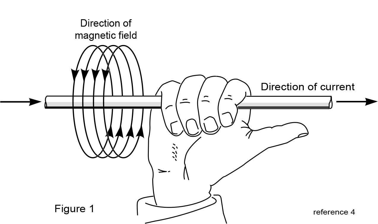
In order to measure current traveling through a wire, a simple clamp-on amp-meter (such as the Fluke camp-on meter shown in the photo below) can be used. In this example, approximately 10 amps of current is flowing through the wire. However, the clamp-on amp-meter is not measuring current flow but is actually measuring the amount of magnetic field around the wire. One of the basic fundamentals of electricity is that when current flows through a wire, a magnetic field is produced around that wire. Figure 1 represents current flow through a wire and the resulting magnetic field.
The rotation of this magnetic field depends on the direction of the current flow. In the late 19th century, John Fleming discovered what is known as the “right-hand rule.” This simple rule states that using your right hand, pointing the thumb in the direction of current flow, the magnetic field will travel around the wire in the direction of the other four fingers.
The intensity of the magnetic field is directly proportional to the amount of current flow. Therefore, the more current that is flowing through the wire, the greater the magnetic field.
The principle of magnetic fields is very important to grasp when trying to understand how to measure AC leakage current using clamp-on meters. These types of meters do not measure current flow. Instead, all clamp-on amp-meters measure the intensity of the magnetic field generated around the wire by the flow of current. Since the magnetic field is directly proportional to the amount of current flow in the wire, the clamp-on meter can be calibrated to display the amount of current in the wire based on the intensity of the magnetic field.
Measuring AC Current
Figure 2 represents a vessel’s shore power cord which is connected to a shore power receptacle rated at 120-volt 30-amp. In this example below, the vessel is pulling a 10-amp load. The black (hot) conductor is supplying 10 amps, while the white (neutral) is returning 10-amps back to the receptacle.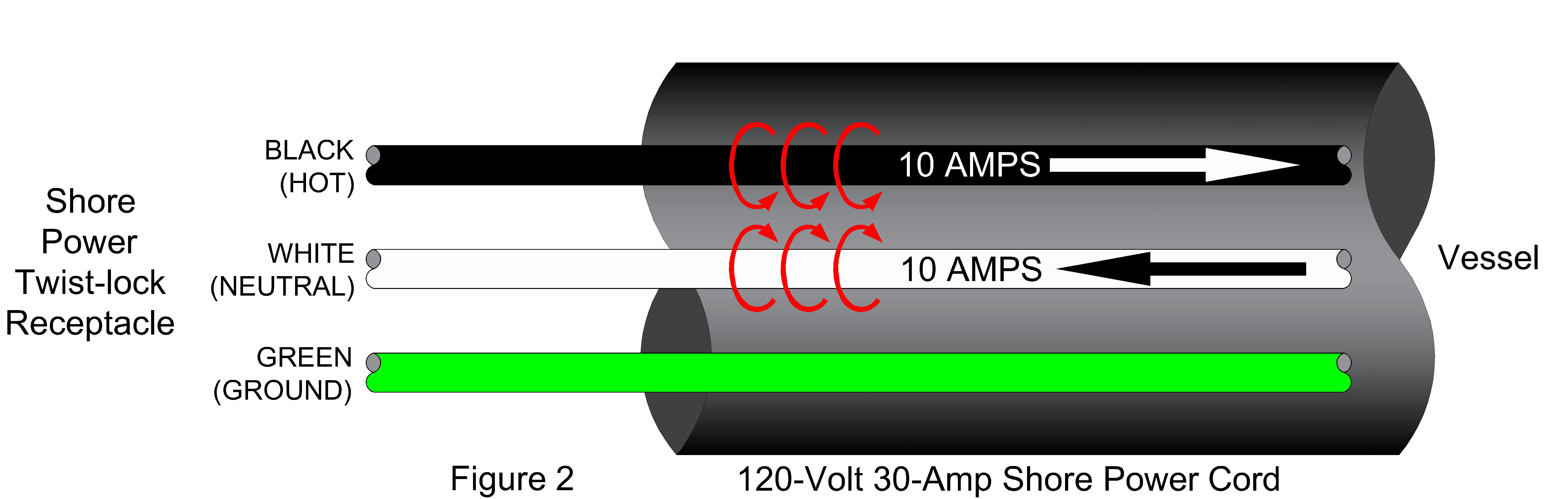
Using Fleming’s right-hand rule, the red arcs represent the direction of magnetic fields in both the black and white wires. If one were to hold his or her right hand up and point the thumb in the direction of the current in the black wire (refer to Figure 1 on page 38), the other four fingers show the direction of the magnetic field. Again, using the right hand, point the thumb in the direction of the current in the white wire. One will find the direction of magnetic field is in the opposite direction.
If a clamp-on meter is used to only measure the current in the black wire, the meter would read the intensity of the magnetic field around the black wire and would be calibrated to display 10-amps on the meter. The same goes for the white wire. If a clamp-on meter is used to only measure the current in the white wire, the meter would read the intensity of the magnetic field around the white wire and would display 10-amps on the meter.
Understanding that a clamp-on amp-meter measures the intensity of the magnetic field, what would happen if the clamp-on meter was clamped around both the black (hot) and white (neutral) wires? As Figure 3 shows, the result would be zero amps. The orange circle represents the clamp-on meter.
The magnetic field in the black wire is running clockwise and counter-clockwise in the white wire. Since the current is equal in both wires, the magnetic fields are also equal, but only running in opposite directions. The magnetic fields are canceling each other when an amp-meter is clamped around both wires. Therefore, the amp-meter can’t detect any magnetic field, registers no current flow, and will therefore display zero amps.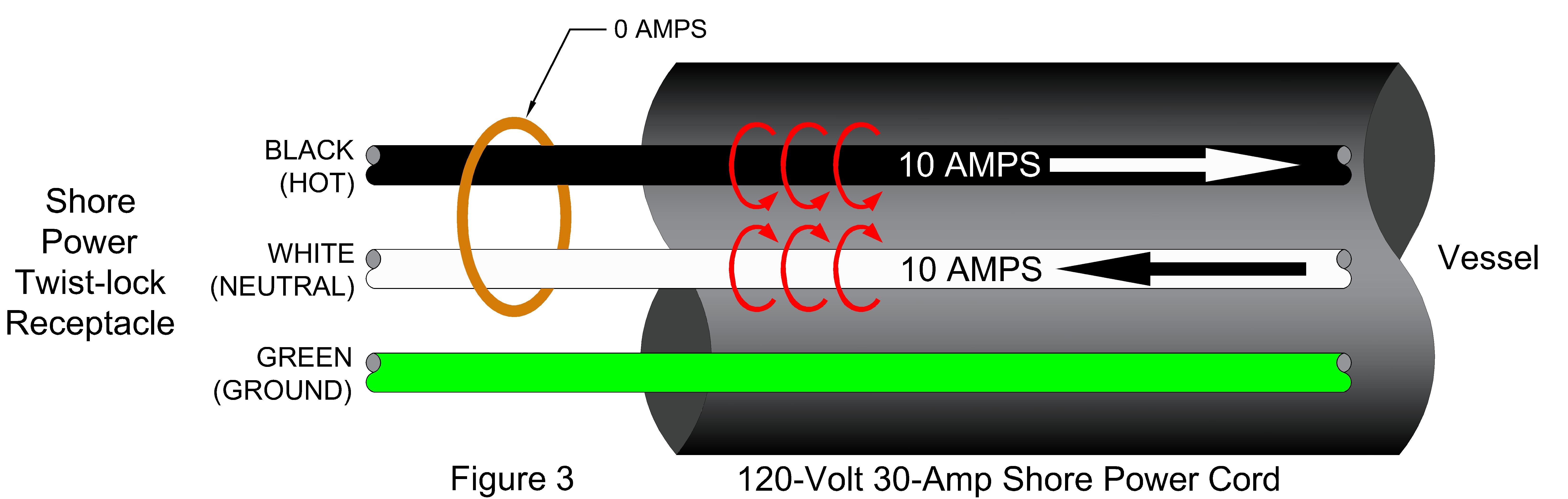
Measuring AC Leakage Current
Consider a more interesting application of this principle in Figure 4. For this example, the black wire has 10 amps, but the white wire only has 9.9 amps.
The intensity of the magnetic field in the white wire is less than the magnetic field in the black wire because of the reduced current in the white wire. 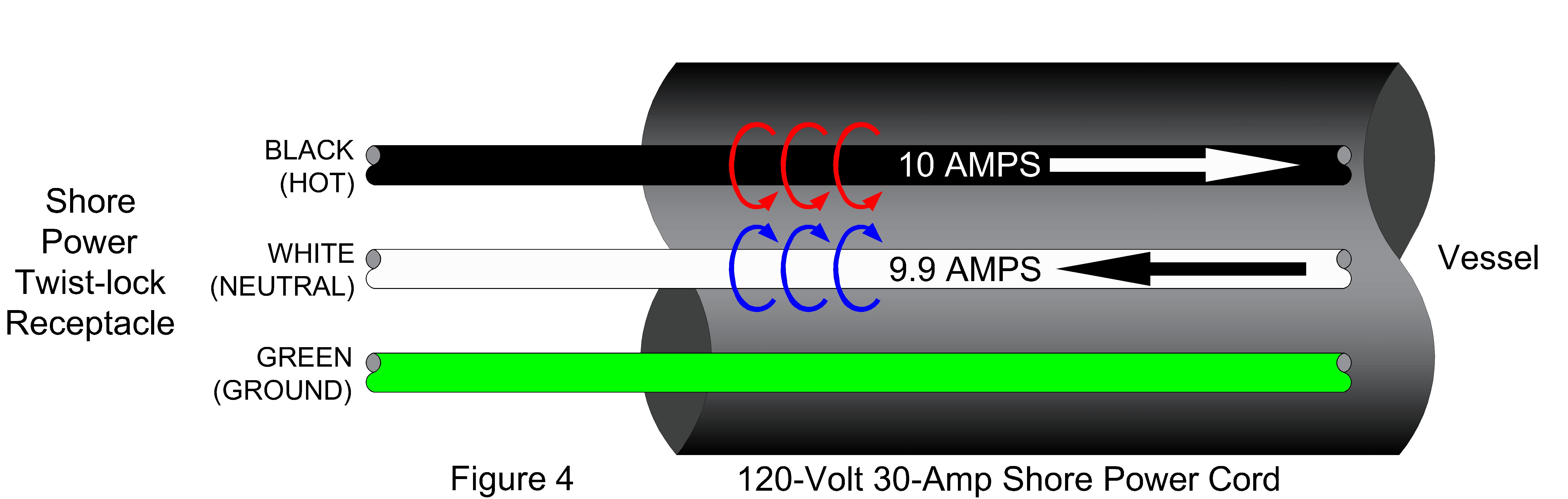 If a clamp-on meter is used to only measure the current in the black wire, the meter would read the intensity of the magnetic field around the black wire and would display 10-amps on the meter. If a clamp-on meter is used to only measure the current in the white wire, the meter would read less magnetic field around the white wire and would display 9.9-amps on the meter.
When a clamp-on meter is clamped around both the black and white wires (refer to Figure 5), the meter will detect the difference in the magnetic fields. This is due to the difference in current flow between the two wires.
In Figure 5, the vessel has 100 mA of leakage current. The definition of leakage current is the current in the return wire (i.e. white or neutral wire) being less than the current in the source (i.e. black or hot) wire.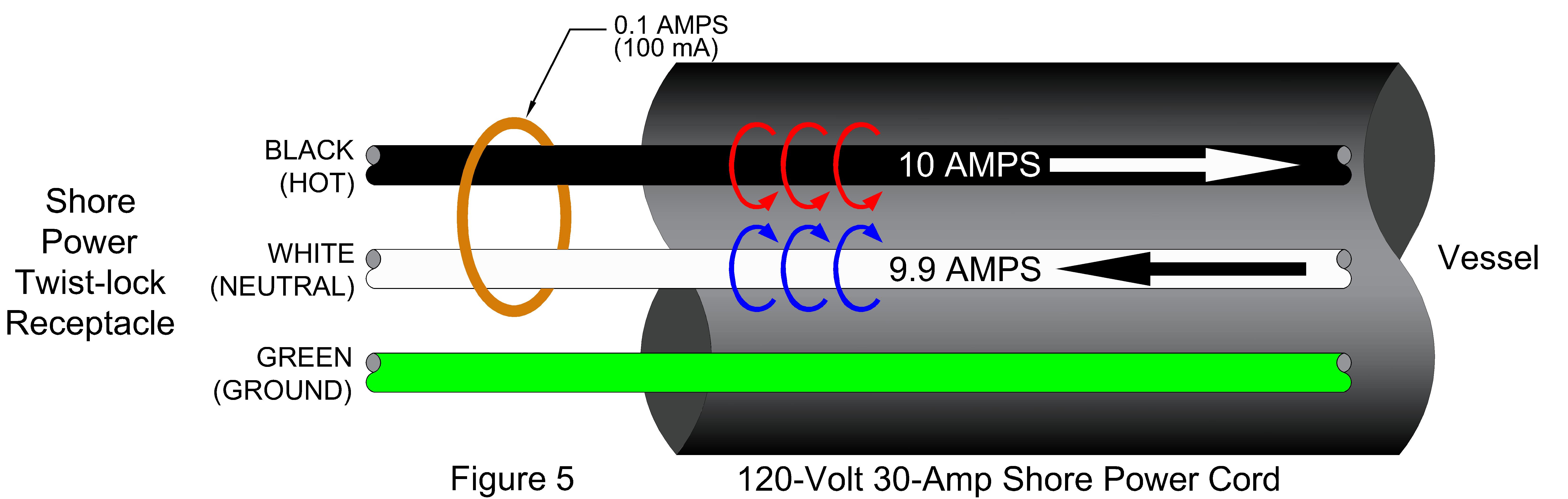
In the marina environment, there are two different scenarios of leakage current. One scenario is illustrated in Figure 6. This example shows the 100 mA of leakage current flowing back to the shore power receptacle on the green (i.e. ground) wire within the shore power cord. Therefore, the leakage current is contained within the shore power cord. 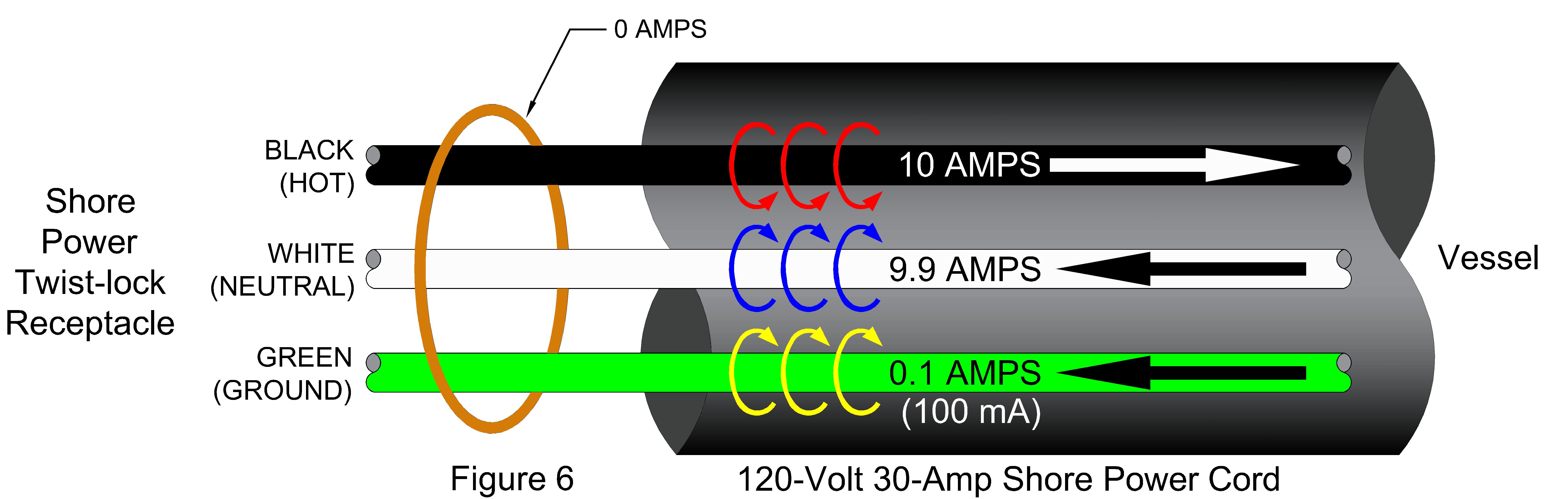 The ground wire should never carry current in normal operation of the electrical system. As shown in this example, if a clamp-on meter is used to clamp on the entire shore power cord, the meter would display zero current because the magnetic field is balanced. In most cases, this scenario of leakage current is a neutral-to-ground connection inside the vessel.
The second scenario of leakage current is illustrated in Figure 7. This scenario typically is more hazardous than the first because the leakage is not contained within the shore power cord but is traveling through another path. The path of leakage current is generally in the environment, (mostly the surrounding water, in the case of marinas). Other path flows could be the metal frame of the dock or communication lines such as telephone or cable TV.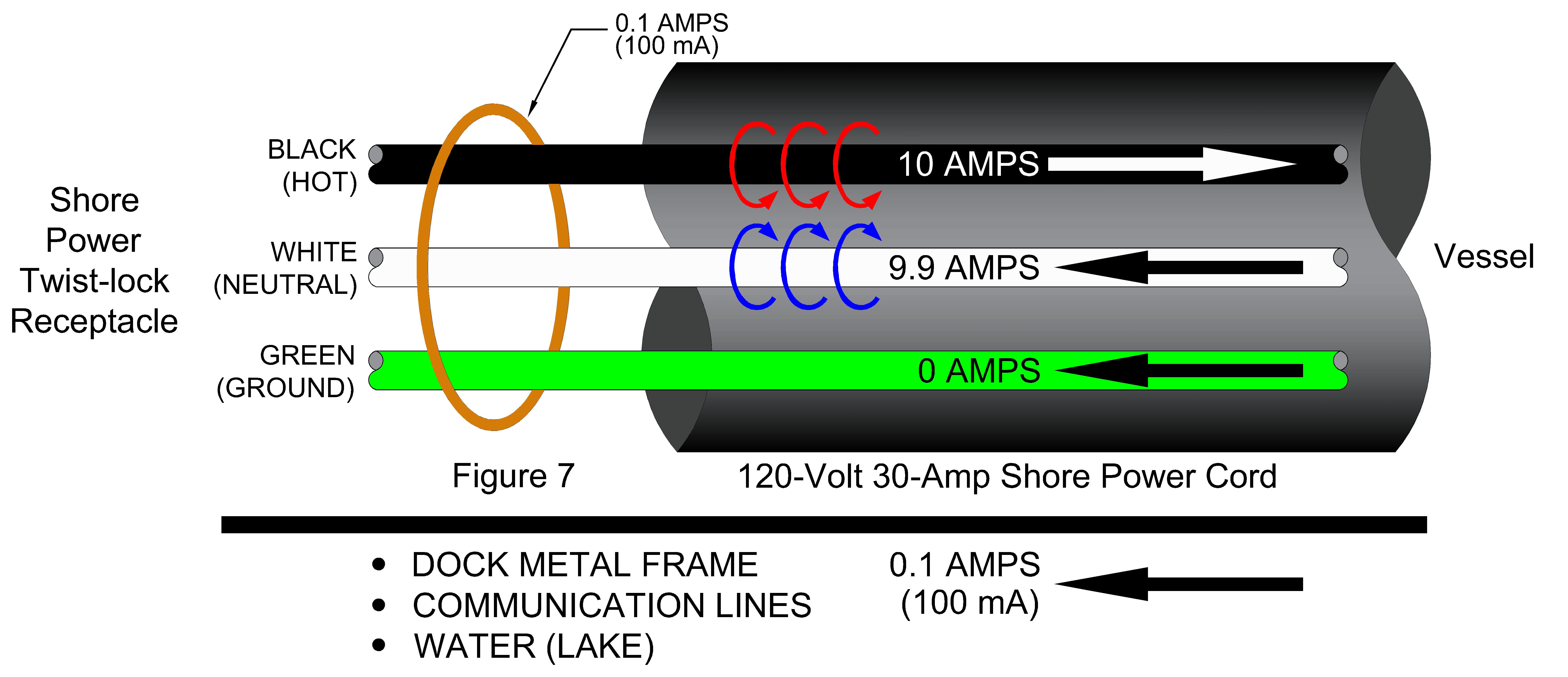
This photo shows the leakage current measurement of a 120-volt 30-amp shore power cord connected to a vessel. Clamping the meter around the entire shore power cord will measure the second scenario of leakage current noted above. As in the example above, the vessel connected to this shore power cord is leaking 100 mA of current into the environment.
When one takes a reading of leakage current, it is like taking a picture at a specific moment in time; after a brief moment in time, the scene changes. This is also true of the photo of the 100 mA reading. As soon as the meter is removed from the shore power cord, the leakage current can change. This is largely due to electrical equipment inside the vessel. For instance, the reading might be lower when the air conditioner is not running and higher when it is running. The same goes for all other pieces of equipment in the vessel.
The best scenario to measure the leakage current of a vessel is when all of the vessel’s electrical equipment is running, including all 120 and 240-volt equipment (including the DC to AC inverter). This will allow the leakage current meter to not only measure the wiring of the vessel, but also all of the electrical systems inside the equipment and fixtures.
The cause of leakage current is beyond the scope of this article. However, in some instances the age of the wiring systems and electrical equipment cause additional leakage current. As the insulation around a wire ages, the insulation properties begin to breakdown. Dry-rotting and cracking of the wire insulation can also cause additional leakage current.
Leakage current is sometimes caused by a high resistance short or a dead short. This scenario would be illustrated as when the black (hot) wire accidently comes into contact with a grounded object. This is called a ground fault. The next section covers ground faults in more detail and explains different levels of ground faults and their hazards to the human body.
The leakage current measurement principle also works identically for a 240-volt 50-amp shore power electrical system.
Ground Faults
A ground fault is defined in the National Electrical Code (NEC) as “an unintentional, electrically conductive connection between an ungrounded conductor of an electrical circuit and the normally non-current-carrying conductors, metallic enclosures, metallic raceways, metallic equipment or earth.”
Such involved and wordy definitions aid in most people having a hard time understanding electrical codes. This definition simply states that the black (hot) wire is leaking current to the grounding system. The grounding system includes the green (ground) wire and everything connected to it such as the aluminum vessel hull or metal structure of the dock.
Every electrical system has leakage current. It is the amount of the leakage current that is of major concern to the marina industry. Small levels of leakage current, typically less than 4 mA, should not cause any safety issues. Levels of leakage current above 4 mA are where safety concerns start to arise.
In order to understand the different levels (or thresholds) of leakage current and safety issues associated with the human body, refer to the table on page 42.
The second line in the current thresholds table (i.e. 4 – 6 mA) is the amount of leakage current that is required for the tripping level of a Ground Fault Circuit Interrupter (GFCI) device. This GFCI device is the most common trip level that most everyone has experience with. A GFCI device is commonly found as a receptacle in your bathroom and kitchen with test and reset buttons on the front of the receptacle. A GFCI receptacle will trip power to the receptacle if there is an imbalance of current on the black (hot) and white (neutral) wires somewhere between 4 to 6 mA.
Any ground fault device that trips power when leakage current is greater than 6 mA is considered a Ground Fault Protection for Equipment (GFPE) device. However, in the NEC Article for marina codes (i.e. Article 555), the “E” is dropped and refers to these devices as Ground Fault Protection (GFP). Therefore, the 2017 NEC – Article 555.3 refers to a GFP device as a device with a leakage current trip level of 30 mA. Based on the information above, one should now understand this means there is a difference in current level between the black (hot) wire and the white (neutral) wire of 30 mA.
In all of the leakage current examples above, there is a 100 mA imbalance of current between the black and white wires. For reference, the previous 2011 and 2014 NEC Editions required a 100 mA GFP on marinas.
Correct Clamp-On Amp Meter Selection
There are many clamp-on amp meters on the market. However, most are not suitable to be used as an AC leakage current meter. Going to a local electrical supply store and purchasing an off-the-shelf clamp-on meter generally is not the meter of choice.
A clamp-on amp meter that should be used to measure AC leakage current should be sensitive enough to measure current accurately to less than 4 mA. If a meter doesn’t have a mA setting and/or it is not labeled with “Leak” or “Leakage Meter,” then it probably isn’t a meter that can read leakage current.
There are several clamp-on amp meters on the market that will properly test for leakage current.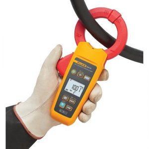
Following is a list of meters that will measure in the low (or lower) mA range:
Yokogawa Clamp-on Tester
Model No.: 30031A/30032A
Leakage current measurement range: 3 mA – 60 A
Diameter of measurable conductor/cable: 40 mm
Amprobe AC Leakage Clamp
Model No.: AC50A
Leakage current measurement range: 0 mA – 60 A
Diameter of measurable conductor/cable: 30 mm
Fluke AC Leakage Current Clamp
Model No.: 369 FC
Leakage current measurement range: 3 mA – 60 A
Diameter of measurable conductor/cable: 60 mm
Fluke AC Leakage Current Clamp Meter
Model No.: 360
Leakage current measurement range: 3 mA – 60 A
Diameter of measurable conductor/cable: 40 mm
Armada Tech True-RMS Milliamp Leakage Clamp Meter
Model No.: PRO93
Leakage current measurement range: <1 mA – 100 A
Diameter of measurable conductor/cable: 28 mm
The only clamp-on meter listed above that will allow the measurement of multiple 50-amp 240-volt shore power cords at one time is the Fluke 369 as it has a 60 mm clamp diameter. This clamp-on will also clamp around a 100-amp shore power cord. This function is useful if a marina has several vessels that have these larger power requirements.
Recommendations on Acceptable Leakage Current
As stated before, all electrical systems have leakage current. The important question to ask is “How much is too much?” Many experts in the electrical field will tell you that any leakage current more than 6 mA is dangerous, and this would be correct. If you refer back to the “Current Thresholds for Humans” chart on this page, muscle contractions can occur with as little as 10 mA. Muscle contractions while swimming can cause drowning.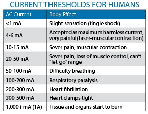
There have been studies conducted to determine the amount of acceptable leakage current for a vessel while plugged in to shore power. The recommendation from the 2008 US Coast Guard report “In-Water Shock Hazard Mitigation” stated: “If AC leakage current is kept to less than 100 milliamps, a dangerous condition should not result around boats connected to the shore power system.”
As a result of this study, the 100 mA GFP requirement was added to the 2011 Edition of the NEC. The same requirement was kept in the 2014 Edition of the NEC.
Many in the code standards panels felt the 100 mA GFP requirement was not enough protection for vessels. Therefore, the American Boat and Yacht Council (ABYC) added a ground fault trip requirement to its E-11 Standard “AC and DC Electrical Systems on Boats” in the 2012 Edition. The following is taken from the ABYC E-11 Standard of July 2015: “11.11.1.1 – The trip level {of the GFP} shall be a maximum of 30mA. The trip time shall be a maximum of 100ms.”
Also, the latest 2017 Edition of the NEC has reduced the GFP requirement from the previous editions. Article 555.3 of the 2017 NEC states:
“The overcurrent protective devices that supply the marina, boatyards, and commercial and noncommercial docking facilities shall have ground-fault protection not exceeding 30 mA.”
Furthermore, the 2008 U.S. Coast Guard report “In-Water Shock Hazard Mitigation” states: “30ma will result in 0.11V/foot. At these low current and voltage gradient levels…there should be no danger to anyone who may be in the water around a boat.”
By no means is this an invitation or otherwise a reason to grant permission to enter the water in a marina, even if the marina is equipped with a 30 mA GFP. Instead, what is being said is that a 30mA GFP should provide enough protection for a person if they accidently fall into the water at a marina.
Less than 30 mA of leakage current for a single vessel is within the acceptable range of safety standards.
Conclusion and Recommendations
The following is a list of recommendations and requirements for consideration:
• Only qualified electrical personnel should perform electrical work on marinas and vessels (including, but not limited to, the measuring of leakage current).
• The proper understanding of how leakage current behaves is a requirement for anyone that desires to measure leakage current.
• Install GFP on a marina’s electrical system per the NEC standards.
• If a marina doesn’t have a GFP system installed, a routine should be started to measure for leakage current. Maintain a written log of the leakage current values for each vessel.
• Per the NEC and ABYC standards noted in this article, a single vessel leaking 30 mA or more is not an acceptable amount of leakage current.
• The most accurate means to measure leakage current is clamping around the hot and neutral conductors (see Figure 5). This can be performed by a qualified person within the shore power pedestal or by using an adaptor that has the individual insulated conductors exposed.
Gary Loftis of Maffett Loftis Engineering, LLC, is registered professional electrical engineer with more than 30 years of experience. For more about the technical bulletin, contact him at gary@maffett-loftis.com.
| Categories | |
| Tags |