
The Devil is in the Details
Published on October 24, 2025


Planners, particularly engineers, spend most of their time worrying about the “what ifs.” Rightly, they should, whether it is considering how the big picture looks and functions, or how the design will stand the test of time. Ironically, the real test is often, “How does my marina work on a day-to-day basis, functionally, socially and economically?” These factors need to be given equal consideration when designing a marina, and perhaps are the most important. Some questions need to be asked and addressed up front. Those can include:
- What is my particular market, and how will I access or service it?
- What vessels am I trying to attract? Sailboats? Runabouts? Cruisers or megayachts?
- Will I offer fuel, or will I want or allow public boat launches in my facility?
- How big of a marina should I have?
- How will I make money from my marina?
Answers to these questions should dictate how you physically plan your marina rather than just dropping a layout of docks onto a water space.
Basic Economics of Sizing a Marina
The ASCE Manual of Practice No. 50 for Small Craft Harbor Design offers an example of where you want to find your sweet spot in planning your facility. The simple math example given compares two hypothetical marina dock options: the first populated by 84 25-foot slips, and the other by only 26 50-foot slips. Considering access and fairway requirements, both require one acre of water space to accommodate those slips. Receiving revenue from 84 slips is undoubtedly better than from just 26. However, that is only one side of the equation. The other side of the equation is that you have to pay for those slips. The 84 slips require approximately 9,200 square feet of dock to be installed, while the 26 large slips require only 7,100 square feet. In the example offered, assuming a 6% financing rate, it turns out your return on investment is nearly double when offering fewer, larger slips.
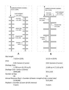
Clearly, you have to make sure you have a market for these larger slips, so you need to do your due diligence about your market, and likely you will need to offer a range in slip sizes, but for pure financial advantage, the larger the average slip size, the better your investment return.
Dockage Arrangement and Orientation
Once you have decided what your boat mix is, you then need to decide how you are going to deploy your slips. Here, engineering does come into play, but so does how a marina socially interacts and whether you are building the facility all at once or in phases.
The orientation of the docks should consider the effects of winds, waves and currents to ensure the best layout from a navigational perspective. For improved navigation, slips should face the dominant natural force to facilitate the easiest ingressing or egressing, rather than battling crosswinds or currents while trying to maneuver at an incredibly low speed. This would imply that in riverine, current-dominated berths, the slip alignment should be parallel with the shore. In a coastal setting where there is predominant onshore-offshore wind or wave action, the slips should be oriented perpendicular to the shore. However, exceptions may be considered if the critical loading on the docks occurs at times when the slips are unoccupied, such as during winter ice events or during spring floods, when the lateral loadings of the floats are the greatest concern. In such a case, the alignment that produces the least loading on the system is preferred.
There are basically two ways that a dock system may be laid out in a marina: either a “traditional,” shore-perpendicular array of docks, each with its own shore landing, or in a “tree” configuration where there is only one or two shore connections and the docks extend outward laterally from a central main pier.
The tree arrangement has a variant, referred to as a “comb,” which is two half-trees with a central access fairway between. These three arrangements are shown in Figures 2a, b and c.
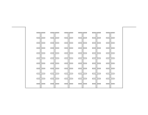
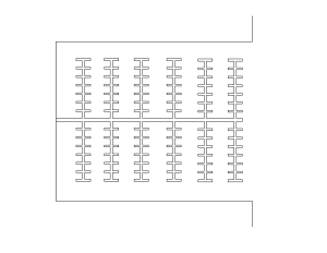
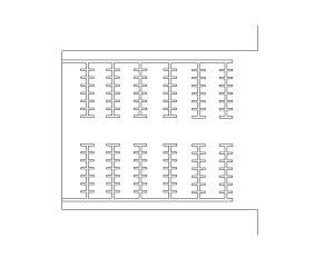
All three schemes offer advantages and disadvantages. Independent of the consideration for alignment against the natural wind, wave and current loadings, the traditional arrangement lends itself to phased growth and expansion of the marina by only building what is currently financially viable. The disadvantage is that electrical costs and other slip services may be more expensive, as some infrastructure may unnecessarily be duplicated on each pier. The tree (and comb) arrangement offers the advantage of better security and access control and lower utility costs, since major utilities can be consolidated on one central spine and then subdivided to be dedicated and sized for one lateral pier of berthing only one vessel size.
Socially, tree arrangement is popular as patrons can more easily move between different docks to visit friends or access toilet facilities without having to leave the secure area. In this way, tree arrangement fosters a more neighborhood-like culture than the traditional configuration. The disadvantage of the tree scheme is that, generally, it is necessary to do a full build-out of slips initially, as the infrastructure needs to be sized anticipating the completed arrangement.
A final consideration in picking your layout is how you envision operating your marina. If you plan to have the fuel pier, do you want it located near your office so you can minimize staffing it? Or is it better to locate it near your entrance so that passing boaters may more readily frequent it and not intermingle transient traffic with your marina traffic? You also need to think about walking distances to various slips and, most importantly, accessibility of toilet facilities. All of these should influence which slip layout configuration will work best for you.
Also, remember that you will have a mix of boat sizes. You are constrained by your available water area, so you want to maximize your return per square foot of that area. The biggest non-revenue-producing water area is the space lost to navigation fairways, so you will want to minimize the area lost to navigation as much as possible. In the upcoming revision to the ASCE Manual 50, guidance is offered to allow for savings in fairway areas by recognizing that in the modern recreational boating fleet, once vessel sizes approach a threshold of 45-50 feet, the vessels are now nearly universally outfitted with bow thrusters and/or other drive systems that allow for much more compact
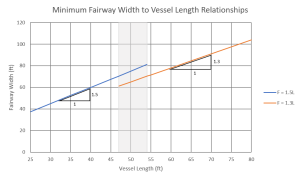
maneuvering in confined waters. This means that the traditional guidance stating that a fairway needs to be at least 150% of the boat length using that fairway may be relaxed in the case of larger vessels, down to a bare minimum of 1.3L as shown in Figure 3. That bare minimum is based on the fact that unless a boat can be ”crabbed” into a space, the center of the turning circle of a boat occurs at about one-third of its length, not at its center. Steering a boat is akin to backing a vehicle, as the steering occurs at the rear, not at the front.
Now that we have squeezed our fairways down to minimize wasted water area, this most likely means that on one side of any headwalk, there will be different-sized boats than on the other. The fairway width itself will be dictated by the largest slip length in that fairway. But what about the slips themselves?
As you lay out the berths along the head pier, inevitably, when you arrive at the T-head, the two sides will not match. This is illustrated in Figure 4, Pier A.
We want an unbroken T-head to allow for oversized berthing there, but
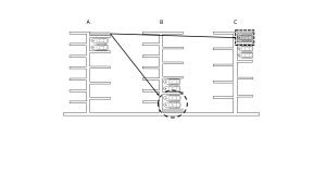
typically, there is excess pier length on one side of the dock. So, what should be done with the excess pier length? It could be distributed back into each berth width, but that is just wasted usage, given the size of boats to be moored therein. Unless you are lucky, the excess is not sufficient to provide for a full single slip, in which case the excess should be applied to the innermost double berth as shown in Pier B. The reasoning is that this slip is the most difficult to maneuver into since the back and turning movement of a boat is restricted in one direction. Adding the excess width in that one double berth allows for an easier entry and egress from that innermost slip.
If there is sufficient dimension to introduce a single slip, as suggested on Pier C, that may have the highest added value and revenue potential, as it is most sought after due to the easiest egress and unshared space. Now, one exception to this guidance is if a marina plans to accommodate catamarans as part of its fleet. In that case, an outer extra-wide outer end single slip is perfect for that multi-hull mooring because of the ease in berthing the wide craft.
Boat Trailer Launch Design
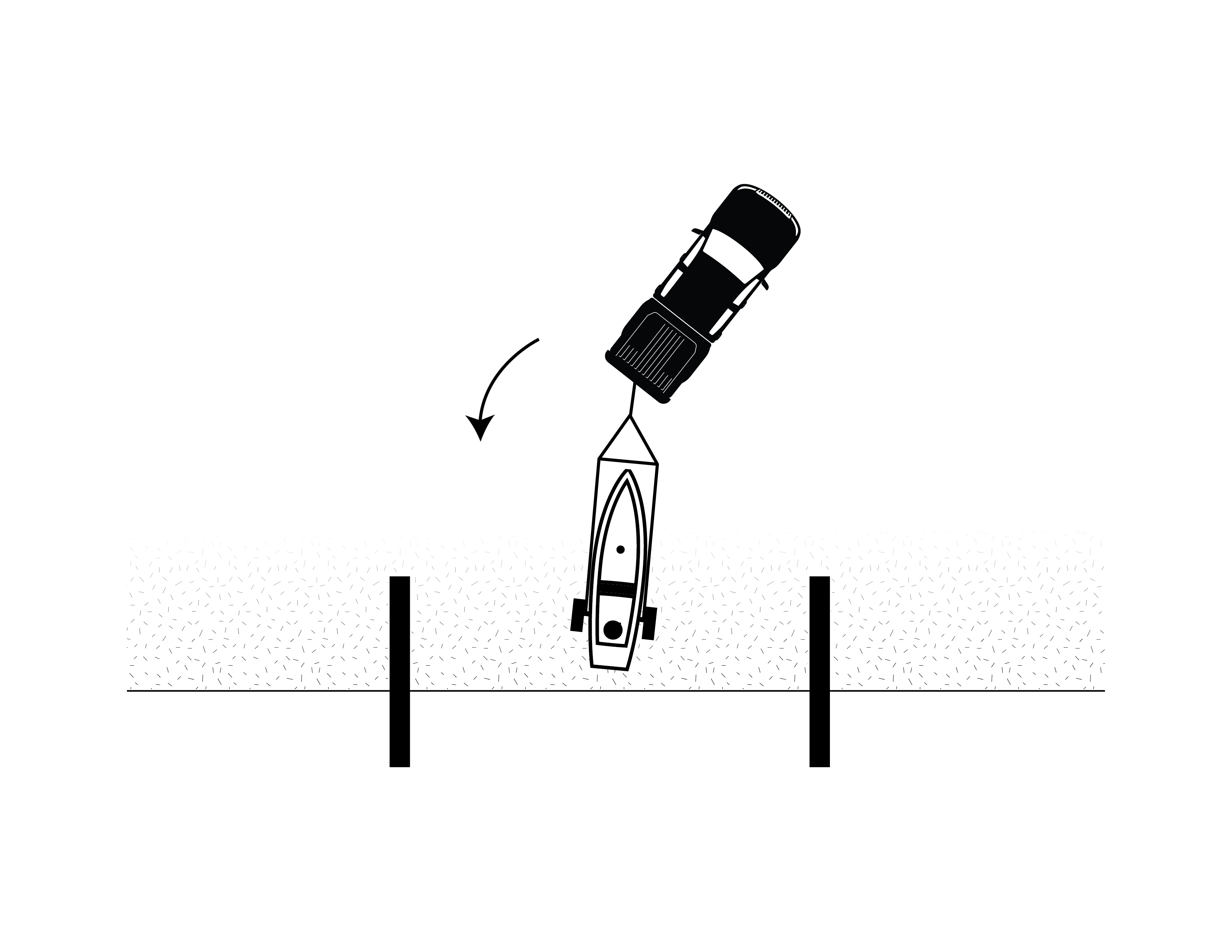
Tobiasson and Kollmeyer, in their book “Marinas and Small Craft Harbors” (2000), offer guidance in the design of boat launch ramps in terms of allowable slopes. Their recommendations are that the desired slope should range between 12.5% (7 degrees, 1v:8h) and 15% (8.5 degrees, 1v:6.7h) so that the vehicle pulling the launch trailer neither becomes partially immersed, nor is overloaded and unstable during haul out. But in laying out a launch ramp, there is a secondary consideration, and that is driver visibility during the launch/haul-out operation.
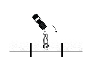
 While most modern vehicles now have rear-view cameras to assist the driver with visibility when backing up, they tend to have a limited field of view, and, sometimes, tailgates or other obstructions may render the camera of little help. The driver is still dependent on a direct line of sight during the launch. For U.S. car designs, the driver’s seat is on the left, which means looking over the right shoulder, out through the rear window, is the least obstructed view.
Trying to look over the driver’s left shoulder and out the side window limits the full field of view to the rear for the driver. Therefore, whenever possible, the launch path should be configured so that the vehicle’s back turning is toward the right, as suggested in Figure 5b. This allows the driver to see through the rear window when backing.
Conclusions
There are plenty of details to think about, and these are just a few of the major ones. These are things your engineer and planner should already be aware of, but they are ultimately determined by your operation. Unfortunately, they directly influence what will be a good marina plan, and what may not. These decisions aren’t like picking the color of doorknobs for a new house, which can be decided later, but need to be thought about from day one, just as important as making sure that your marina is built strong, durable and safe.
Jack Cox is principal/vice president of engineering at Edgewater Resources. He can be reached at jcox@edgewaterresources.com.

| Categories | |
| Tags |